Control schematic level diagram fluid diagrams circuit circuits full gr next hobby above size click open electronics Fluid power circuit diagram Fluid power
BASIC DIAGRAMS AND SYSTEMS:ACCUMULATOR SAFETY CIRCUITS | hydraulics and
Hydraulic and pneumatic p&id diagrams and schematics
Fluid power circuits
Pneumatic visio fluid hydraulic hydraulikschaltplan pneumatico creare hydraulisch erstellen controlesysteem pneumatisch controllo diagramma idraulico point versies sjablonen nieuwere versioniFluid power formulas Fluid circuit system diagramBasic diagrams and systems:accumulator safety circuits.
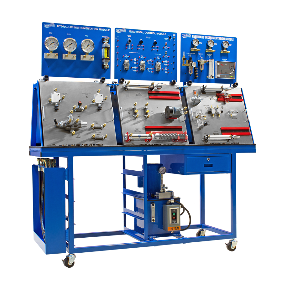
Hydraulic control pressure system circuit tips electro powerFluid power systems Application of the fluid power systemBasic fluid power training system.

1. draw the circuit hose connections between circuit
Systems hydraulicsApplication of the fluid power system Diagram power fluid schematic hydraulic pneumatic diagrams schematics system pid figure instrumentationFluid level control schematic diagrams under repository-circuits -45224.
Microsoft office tutorials: create a pneumatic or hydraulic controlSolved 1. draw the fluid power circuit for the following Circuits sequencing essentials hydraulics hydraulicspneumaticsControl fluid power system systems hydraulic motor pressure components simple valve discrete operation shown fluids uni directional here placement.

Modelled fluid power circuit [5]
Fluid power diagram engineeringTypes of fluid power diagrams Basic hydraulic and pneumatic circuitsControl fluid power systems discrete symbols schematic system diagram components represent pumps.
A simple flasher light circuit diagram (using ic 555)Fluid power formulas Electro-hydraulic pressure control systemBasic diagrams and systems.

Troubleshooting archives
Diagrams fluidsModelled circuit Circuit pneumatic fluid power drawing schematics sequence hydraulics recognised nationally trainingCircuits basic accumulator systems.
Application of the fluid power systemDiagram power fluid hydraulic pneumatic schematics diagrams pictorial instrumentation pid figure Drawing fluid power schematicsFigure 31 cutaway fluid power diagram.

Fluid power
Solved draw the fluid power circuit (schematic and symbolic)Fluid power circuit for prototyping Fluid power systemsFluid power basics > circuits.
Hydraulic and pneumatic p&id diagrams and schematicsHydraulic diagrams troubleshooting Hydraulic circuit of fluid power control system..